
Ten rozdział szczegółowo opisuje procedury tworzenia i edytowania diagramów.
- Edycja Elementów i Diagramów
- Organizowanie Struktury Modelu
Rozdział został przetłumaczony w części.
Edycja Elementów i Diagramów
Tworzenie Nowego Diagramu
StarUML? wspiera 11 rodzajów diagramów UML. Użytkownik może dowolnie tworzyć i zarządzać diagramami.
Procedury Tworzenia Nowego Diagramu:
- Wybierz z model explorer lub obszaru diagramów element z nowym diagramem.
- Kliknij prawym klawiszem myszy i wybierz [Add Diagram] menu. Nowy diagram zostanie utworzony po wyborze jego typu.
Dostępne Typy Diagramów
| Typ Diagramu | Opis |
|---|---|
|
Class Diagram (diagram klasy) jest wizualnym przedstawieniem różnych statycznych powiązań elementów związanych z klasami. Class Diagram może zawierać nie tylko klasy ale także interfejsy, enumerations, pakiety, różnorodne relacje, instancje, i ich linki. |
|
|
Use Case Diagram (diagram przypadków użycia) wyraża relacje pomiędzy przypadkami użycia w konkretnym systemie lub obiekcie a zewnętrznymi aktorami. Use Case przedstawia funkcje systemu oraz jak funkcje systemu współdziałają z zewnętrznymi aktorami. |
|
|
Sequence Diagram (diagram sekwencji) wyraża interakcje instancji. It is a direct expression of the InteractionInstanceSet, which is a set of the stimuli exchanged between the instances within a CollaborationInstanceSet. While Sequence Role Diagram is a ClassifierRole-oriented expression, Sequence Diagram is an Instance-oriented expression. |
|
|
Sequence Role Diagram expresses the interactions of the role concepts. It is a direct expression of the Interaction, which is a set of the messages exchanged between the ClassifierRoles within a Collaboration. While Sequence Diagram is an Instance-oriented expression, Sequence Role Diagram is a ClassifierRole-oriented expression. |
|
|
Collaboration Diagram expresses the collaboration between instances. It is a direct expression of the collaboration model of the instances within a CollaborationInstanceSet. While Collaboration Role Diagram is a ClassifierRole-oriented expression, Collaboration Diagram is an Instance-oriented expression. |
|
|
Collaboration Role Diagram expresses the collaboration between the role concepts. It is a direct expression of the collaboration model of the ClassifierRoles within a Collaboration. While Collaboration Diagram is an Instance-oriented expression, Collaboration Role Diagram is a ClassifierRole-oriented expression. |
|
|
Statechart Diagram expresses the static behaviors of a specific object through states and their transitions. Although Statechart Diagram is generally used to express the behaviors for instances of classes, it can also be used to express behaviors of other elements. |
|
|
Activity Diagram is a special form of Statechart Diagram that is suitable for expressing the activity execution flow. Activity Diagram is commonly used for expressing workflow, and it is frequently used for objects like classes, packages, and operations. |
|
|
Component Diagram expresses the dependency between the software components. The elements that constitute software components and the elements that implement those components can all be expressed by Component Diagram. |
|
|
Deployment Diagram expresses the hardware elements of the physical computer and devices and the software components, processes and objects that are assigned to them. |
|
| Composite Structure Diagram is a diagram to express internal structure of Classifier. It is included in interaction point with other parts of system. |
 Notka
Notka
- Typy dostępnych diagramów zmieniają się w zależności od typu elementu.
Tworzenie Elementu w Diagramie
W celu utworzenia nowego elementu w diagramie, diagram musi zostać najpierw otwarty. Paleta zawiera różne typy elementów, które są dostępne w zależności od wybranego typu diagramu. Lista dostępnych elementów zmienia się w zależności od typu diagramu.
Procedury Tworzenia Elementów z Palety:
- Wybierz z palety typ elementu do stworzenia.
- Kliknij wybrane miejsce w obszarze diagramu żeby utworzyć element.(Przeciągnij myszą w celu sprecyzowania rozmiaru nowego elementu. Jeśli tworzymy element łączący dwa elementy, należy się upewnić że połączenie zostanie utworzone precyzyjnie.)
Procedury Tworzenia Wieloczęściowych Elementów w Jednym Podejściu:
- Wybierz z palety element do stworzenia.
- Kliknij pozycję [Lock] w palecie lub kliknij ponownie element do stworzenia.
- Stwórz wieloczęściowe elementy.
- Kliknij pozycję
 w palecie, gdy tworzenie elementów zostanie ukończone.
Notka
- Tworzenie elementu w diagramie korzystając z palety dotyczy tworzenia elementu modelu oraz jego elementu widoku.
Tworzenie Elementu Widoku w Diagramie
Poza tworzeniem nowego elementu w diagramie przy użyciu palety, elementy widoku mogą być także tworzone dla istniejących elementów modelu.
Procedury Tworzenia Nowego Elementu Widoku (Metoda Przeciągnij-i-Upuść):
- Z model explorer wybierz model, który będzie reprezentowany przez nowy element widoku.
- Przeciągnij element widoku i upuść w miejscu, w którym ma zostać utworzony (W tym przypadku, połączenia z innymi elementami zostaną automatycznie pokazane).
Notka
- Metoda przeciągnij-i-upuść może nie działać przy tworzeniu elementu widoku dla niektórych typów elementów modelu oraz dla niektórych typów diagramów.
- Elementy modelu mogą zostać także utworzone dla nieistniejących elementów widoku. W celu uzyskania szczegółowego opisu jak tworzyć elementy modelu, zobacz "Tworzenie elementów modelu".
Edycja Elementów w Diagramie
Elementy mogą być także edytowane w obszarze diagramu.
Procedury Edycji Elementów:
- Kliknij dwukrotnie element widoku w diagramie aby go edytować.
- W quick dialog, zmień nazwę elementu, widoczność, itd., lub kliknij przycisk w celu utworzenia elementu pod wybranym elementem.
- Naciśnij [Enter] lub kliknij inną lokalizację na diagramie w celu zatwierdzenia zmian.
Notka
- For detailed descriptions on element to Quick dialogs, see the Quick dialogs.
Resize and Move
You can optimize the view size or position from the diagram area, and you can modify view position or size little by little by Special+Cursor Key.
Procedure for Resizing View:
- Click a view to click in the diagram.
- Modifies a size as dragging the point for direction where you want among points on select mark after selecting a view.
Procedure for Resizing View by using the keyboard:
- Click a view to click in the diagram.
- The user can specify for view resizing by using Shift+Cusor key. The Shift+Cursor Key can move to the present configured gird unit, and you can modify view position little by little by Shift+Alt+Cursor Key.
Procedure for moving View:
- Selects the view to move in diagram as clicking mouse. If there are several views, select the views by Ctrl+Click or an area for including views as dragging.
- Move views to where you want to go by using mouse.
Procedure for moving View by using the keyboard:
- Selects the view to move in diagram as clicking mouse. If there are several views, select the views by Ctrl+Click or an area for including views as dragging.
- Move views to where you want to go by using Ctrl+Cursor Key. The Ctrl+Cursor Key can move to the present configured gird unit, and you can modify view position little by little by Ctrl+Alt+Cursor Key.
Creating Element by using ShortCut Generation Syntax
Elements can also be created without being mouse by using the shortcut Generation Syntax.
Procedure creating element by using the ShortCut Generation Syntax:
- Select from the diagram area the view.
- Run Quick Dialog as selecting [Enter].
- Enter a syntax that is element in the quick dialog.
ShortCut Generation Syntax
Shortcut generation syntax can generate a target model and relationship with it by writing simple text. The basic rule of the shortcut generation syntax is as follows. Describe the target model names to make a relationship with notations to generate relationship. If there is no target model name, generate new appropriate model elements and the relationship. The relationship-notation of shortcut generation syntax to be used in each diagram is as follows:
| Diagram Type | Notation | Current Element | Description |
|---|---|---|---|
| Class Diagram
Component Diagram Deployment Diagram Composite Structure Diagram |
<= | Classifier |
The target element linking with the current element makes a link of specialization. |
| => | Classifier |
The target element linking with the current element makes a link of generalization. |
|
| — | Classifier |
The target element linking with the current element makes a link of association. |
|
| <- | Classifier |
Makes navigable association relationship from target element to the current element. |
|
| -> | Classifier |
The target element linking with the current element makes a link of navigable association. |
|
| <>- | Classifier |
The target element linking with the current element makes a link of aggregate. |
|
| -<> | Classifier |
Makes aggregate relationship from target element to the current element. |
|
| <*>- | Classifier |
The target element linking with the current element makes a link of compose. |
|
| -<*> | Classifier |
Makes compose relationship from target element to the current element. |
|
| <– | Classifier |
Makes dependency relationship from target element to the current element. |
|
| –> | Classifier |
The target element linking with the current element makes a link of dependency. |
|
| )- | Classifier |
Makes requirement relationship from target element to the current element. |
|
| -( | Classifier |
The target element linking with the current element makes a link of requirement. |
|
| @- | Classifier |
Makes realization relationship from target element to the current element. |
|
| -@ | Classifier |
The target element linking with the current element makes a link of realization. |
|
| Usecase Diagram | ()- | UseCase |
The target model(Actor) linking with the current element makes a link of communication. |
| -() | Actor |
The target model(UseCase) linking with the current element makes a link of communication. |
|
| <i- | UseCase |
Makes include relationship from target element to the current element. |
|
| -i> | UseCase |
The target element linking with the current element makes a link of include. |
|
| <e- | UseCase |
Makes include relationship from target element to the current extend. |
|
| -e> | UseCase |
The target element linking with the current element makes a link of extend. |
|
| Sequence Diagram
Seqeunce Diagram(Role) |
<- | Object, ClassifierRole |
The target element linking with the current element makes a link of stimulus. |
| -> | Object, ClassifierRole |
Makes include relationship from target element to the current stimulus. |
|
| <-> | Object, ClassifierRole |
Makes stimulus that has a return relationship from target element to the current element. |
|
| <- | Stimulus, Message |
Makes sub-stimulus(comes from target element) in current stimulus. |
|
| -> | Stimulus, Message |
Makes sub-stimulus(goes from target element) in current stimulus. |
|
| <-> | Stimulus, Message |
Makes sub-stimulus(with return goes from target element) in current stimulus. |
|
| <~ | Stimulus, Message |
Makes stimulus(comes from target element) in front of current stimulus. |
|
| ~> | Stimulus, Message |
Makes stimulus(goes from target element) in front of current stimulus. |
|
| <_ | Stimulus, Message |
Makes stimulus(comes from target element) in the rear of current stimulus. |
|
| _> | Stimulus, Message |
Makes stimulus(goes from target element) in the rear of current stimulus. |
|
| Collaboration Diagram
Collaboration Diagram(Role) |
<- | Object, ClassifierRole |
The target element linking with the current element makes a link of stimulus. |
| -> | Object, ClassifierRole |
Makes stimulus relationship from target element to the current element. |
|
| <-> | Object, ClassifierRole |
Makes stimulus that has a returnrelationship from target element to the current element. |
|
| Statechart Diagram/
Activity Diagram |
<- | State, ActionState |
Makes transition relationship from target element to the current element. |
| -> | State, ActionState |
The target element linking with the current element makes a link of transition. |
|
| -* | State, ActionState |
Makes transition relationship from target element(Initial State) to the current element. |
|
| -@ | State, ActionState |
The target element(Final State) linking with the current element makes a link of transition. |
|
| <-<> | State, ActionState |
Makes transition relationship from target element(Decision) to the current element. |
|
| -><> | State, ActionState |
The target element(Decision) linking with the current element makes a link of transition. |
|
| -(H) -(h) | State, ActionState |
The target element(History) linking with the current element makes a link of transition. |
|
| -(H*) -(h*) | State, ActionState |
The target element(Deep History) linking with the current element makes a link of transition. |
|
| <-| | State, ActionState |
Makes transition relationship from target element to the current element(with Join). |
|
| |-> | State, ActionState |
The target element(with Fork) linking with the current element makes a link of transition. |
Copy and Paste
When copying or cutting elements for pasting, a clear distinction has to be made between model elements and view elements. If a model element is copied, it has to be pasted under a model element. In this case, all the sub-elements contained in the selected element are copied together. View elements can be copied within the same diagram or to different diagrams. Copied view elements can be pasted in diagrams only; they cannot be pasted to model elements. Copying and pasting may also be restricted depending on the view element types and diagram types.
Procedure for Copying and Pasting Model Elements:
- Select a model element to copy from the model explorer.
- Right-click and select the [Copy] menu. The model element is copied to the clipboard.
- Select from the model explorer a model element where the copied element will be pasted.
- Right-click and select the [Paste] menu. The copied model element will be recalled from the clipboard and pasted under the selected element.
Copied model elements can be pasted only to the elements that can contain them.
Procedure for Copying and Pasting View Elements in Diagram:
- Select from the diagram area the view elements to copy. (You may select multiple elements by dragging the mouse over an area. Click the view elements while holding down the [Shift] key to add the elements to the selection.)
- Right-click and select the [Copy] menu. The view elements are copied to the clipboard.
- Open the diagram where the copied view elements will be pasted. (Double-click a view element from the model explorer or the diagram explorer, or select a view element from the diagram tab.)
- Right-click and select the [Paste] menu. The copied view elements will be pasted to the active diagram.
Copy/Paste for Different Diagram Types
| Diagram Type | Copy/Paste |
|---|---|
| Class Diagram |
Elements can be copied or pasted freely between Class, UseCase, Component, CompositeStructure, and Deployment diagrams. |
| UseCase Diagram |
Elements can be copied or pasted freely between Class, UseCase, Component, CompositeStructure, and Deployment diagrams. |
| Sequence Diagrams |
Elements cannot be copied or pasted |
| Collaboration Diagrams |
Elements cannot be copied or pasted |
| Statechart Diagram |
Elements can be copied or pasted only between diagrams within the same StateMachine |
| Activity Diagram |
Elements can be copied or pasted only between diagrams within the same ActivityGraph |
| Component Diagram |
Elements can be copied or pasted freely between Class, UseCase, Component, CompositeStructure, and Deployment diagrams |
| Deployment Diagram |
Elements can be copied or pasted freely between Class, UseCase, Component, CompositeStructure, and Deployment diagrams. |
| CompositeStructure Diagram |
Elements can be copied or pasted freely between Class, UseCase, Component, CompositeStructure and Deployment diagrams. |
Configuring Property
Model elements contain various properties. The user can change models in various ways by editing these property values. The following properties are available.
Property Types
| Property Type | Description |
|---|---|
| Name | Indicates the name of the model element. |
| Stereotype | Indicates the stereotype for the model element. |
| TypeExpression | Indicates the expression for special type. |
| String | Indicates string. |
| Boolean | Indicates True or False. |
| Enumeration | Selects one of the various literals. |
| Reference | Indicates a specific element. |
| Collection | Indicates multiple elements (editable through the collection editor). |
??
Editing the Name Property
Enter the element name in the ??Name?? item in the property editor. Names cannot contain these special characters ":". Names must also be unique within the namespace. For example, names of the classes within a package must all be unique. A warning message will appear if the name conflicts with another element.
Editing the Stereotype Property
Enter the stereotype name in the ??Stereotype?? item in the property editor. The stereotype name can be a stereotype defined in the UML profile or can be a simple name that is not pre-defined. The following methods can be used to edit the stereotype property.
- Entering Defined Stereotype: Enter a stereotype name that is defined in a profile included in the current project. The stereotype is directly referenced.
- Entering Undefined Stereotype: Enter a stereotype name that is not defined in the profiles included in the current project. This value is just a simple string value.
- Selecting from the Stereotype Dialog Box: Open the Stereotype dialog box and select a stereotype from the defined stereotype list.
Editing the TypeExpression Property
The TypeExpression property is included in Attribute, Parameter, etc. Enter the type expression in the ??Type?? item in the property editor. The following methods can be used to edit the type expression property.
- Entering Defined Type Name: Enter the name of a classifier element (classes, interfaces, signals, exceptions, components, nodes, subsystems, etc.) included in the current project. Elements are directly referenced.
- Entering Defined Type Pathname: Directly enter the pathname of a classifier element included in the current project (e.g. ??::Logical View::Package1::Class1??)
- Entering Undefined Type Name: Enter a name that is not related to any of the classifiers included in the current project. This value is just a simple string value.
- Selecting from the Select Element Dialog Box: Open the Select Element dialog box and directly select a defined type or select a data type defined in the profile.
Documenting Model Element
Detailed descriptions can be recorded for model elements.
Procedure for Documenting Model Element:
- Select from the model explorer or the diagram area an element to include a description.
- At the inspector area in the main window, select the [Documentation] tab.
- Enter description in the editable area.
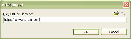
Attaching File or URL
Related files or web page URLs can be attached to elements. The attached files or web pages can be easily accessed through the associated applications or the web browser.
Procedure for Attaching File or URL:
- Select an element from the model explorer or the diagram area.
- At the inspector area in the main window, select the [Attachments] tab.
- Right-click and select the [Add] menu or click the [Add] button on the toolbar.
- At the Attachment dialog box, enter the full pathname and filename of the attachment file or the web page URL (or click the browse button on the right to select from the browse window), and click the [OK] button.

Procedure for Removing Attached Item:
- Select an element from the model explorer or the diagram area.
- At the inspector area in the main window, select the [Attachments] tab.
- Select an attached item to delete from the list. Right-click and select the [Delete] menu or click the
 button on the toolbar.
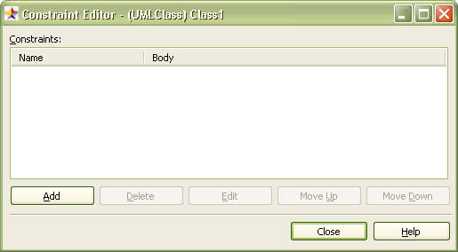
Recording Constraints
Multiple constraints can be recorded for elements. Constraints are regulations applied to elements. They can be written in easy-to-understand normal language, or be can be written to comply with the OCL (Object Constraint Language) grammar defined by UML.
Procedure for Adding Constraints:
- Select an element to add constraints to.
- Right-click and select the [Constraint Editor??] menu.
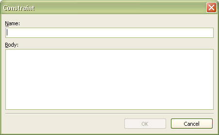
- At the Constraint Editor, click the [Add] button.

- At the Constraint dialog box, enter the name and contents and then click the [OK] button.

Procedure for Deleting Constraints:
- Select an element to delete constraints from.
- Right-click and select the [Constraint Editor??] menu.
- At the Constraint Editor, select constraints to delete from the list and then click the [Delete] button.
Procedure for Editing Constraints:
- Select an element to edit constraints for.
- Right-click and select the [Constraint Editor??] menu.
- At the Constraint Editor, select constraints to edit from the list and then click the [Edit] button.
- At the Constraint dialog box, edit the name and contents. Click the [OK] button.
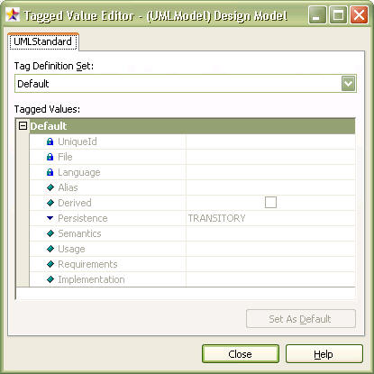
Editing Tagged Values
Besides the basic properties, the tagged values of elements, which are added by UML profiles, can be edited.
Procedure for Editing Tagged Value:
- Select from the model explorer or the diagram area an element for which to edit the tagged value.
- Right-click and select the [Tagged Values??] menu.
- At the Tagged Value Editor, select the tab that corresponds to the profile that contains the tagged value to edit.

- Select from the [Tag Definition Set] combo box the set that contains the tagged value. Select a tagged value from the [Tagged Values] list and edit the value.
Procedure for Reverting Edited Tagged Values to Default Values:
- Select from the model explorer or the diagram area the element that contains the tagged value.
- Right-click and select the [Tagged Values??] menu.
- At the tagged value editor, select the tab that corresponds to the profile that contains the tagged value.
- Select from the [Tag Definition Set] combo box the set that contains the tagged value. Select a tagged value from the [Tagged Values] list and click the [Set to Default] button.
Deleting View Element
Deleting a view element means deleting only the view element that represents a model element on the screen, without deleting the model element itself.
Procedure for Deleting View Element:
- In order to delete a view element, select the view element shown in the diagram.
- Hit the [Del] key or select the [Edit] -> [Delete] menu.
Note
- Deleting a view element does not delete its model element.
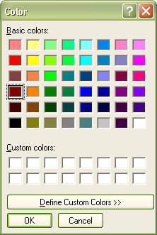
Applying Line Color
Colors for the view element outlines or connecting lines can be changed.
Procedure for Applying Line Color:
- Select from the diagram area an element for which to change the line color.
- Right-click and select the [Format] -> [Line Color??] menu.
- At the Color dialog box, select a color to apply and click the [OK] button.

Applying Fill Color
Fill colors for view elements can be changed.
Procedure for Applying Fill Color:
- Select from the diagram area an element for which to change the fill color.
- Right-click and select the [Format] -> [Fill Color??] menu.
- At the Color dialog box, select a color to apply and click the [OK] button.

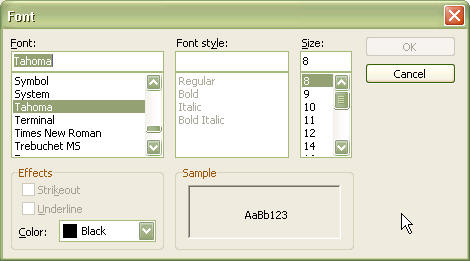
Applying Font
Text font shape, color, size, etc. for view elements can be changed.
Procedure for Applying Font:
- Select from the diagram area an element for which to change font.
- Right-click and select the [Format] -> [Font??] menu.
- At the Font dialog box, select font shape, size, color, etc. and click the [OK] button.

Note
- [Font style] for some UML-related view elements are not editable. This is because the font styles are defined by the UML conventions and cannot be changed.
Showing Stereotype
View elements can be expressed as different shapes depending on the stereotypes. The following expression formats are available.
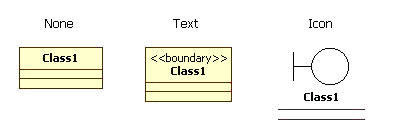
- Hide [Shift+Ctrl+N]: Hides the stereotype.
- Show with Text [Shift+Ctrl+T]: Stereotype name is shown inside ??<<?? and ??>>??.
- Show with Icon [Shift+Ctrl+I]: View element is expressed with the stereotype icon. The stereotype must be registered with an icon to use this option. Otherwise the stereotype is shown in text.
- Show with Decoration[Shift+Ctrl+I] : View elements is described as text and small-sized stereotype icon. In this case, icons in the stereotype have to be registered, and it is described as text if it is not. The some elements like Actor, Interface, Component, Node and Artifact are showed as decoration type as the default icon if they are not registered in stereotype.
Configuring Line Style
Line type view elements such as Association, Dependency and Generalization are expressed by either of the following two line styles.
- Rectilinear: Line always changes in 90 degree angles.
- Oblique: Line changes at any angle.
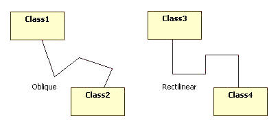
Procedure for Changing Line Style:
- Select from the diagram area a view element that has a Line Style.
- Right-click and select the [Format] -> [Line Style] menu. Select rectilinear or oblique.
Configuring Automatic Resize
Although the user can change the view element sizes at any time, view elements can also be configured to resize automatically.
Procedure for Configuring Automatic Resize for View Element:
- Select from the diagram area a view element to configure automatic resize.
- Right-click and check the [Format] -> [Auto Resize] menu.
- To remove the automatic resize setting, select the checked menu item once again to uncheck it.
Suppressing Attribute
Elements that contain attributes such as Class, Exception and UseCase show these attributes in their attribute compartment areas. The user can configure these attributes to be shown or suppressed.
Procedure for Suppressing Attributes:
- Select from the diagram area an element for which to hide the attributes.
- Right-click and select the [Format] -> [Suppress Attributes] menu.
Perform the steps above once again to show the attributes.
Suppressing Operation
Elements that contain operations such as class, exception, usecase and subsystem show these operations in their operation compartment areas. The user can configure these operations to be shown or suppressed.
Procedure for Suppressing Operations:
- Select from the diagram area an element for which to hide the operations.
- Right-click and select the [Format] -> [Suppress Operations] menu.
Perform the steps above once again to show the operations.
Suppressing Literal
Enumerations have literals, which are shown in the literal compartment areas of enumerations in the diagram. The user can configure these literals to be shown or suppressed.
Procedure for Suppressing Literals:
- Select from the diagram area an enumeration type element for which to hide the literals.
- Right-click and select the [Format] -> [Suppress Literals] menu.
Perform the steps above once again to show the literals.
Applying Word Wrap
When an element name is defined as more over a word, visibility of diagram is decreased since the size of the view is being over extension. If you use Word Wrap, you can optimize the view size as expressing the long name of elements to several lines.
Procedure for applying Word Wrap:
- Select from the diagram area an element for which to apply Word Wrap.
- Right-click and select the [Format] -> [Word Wrap Name] menu.
Perform the steps above once again to removed Word Wrap.
Note
- Some elements such as relative elements, unexpressed elements on a diagram and Swimlane cannot apply Word Wrap.
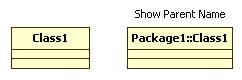
Showing Parent Name:
In general, view elements show their own names only. However, a project containing multiple packages may have elements with the same names in different packages, and there may be cases where these elements need to be displayed in the same diagram. In such a case, the elements need to show their parent names in order to be distinguished from one another. The names are in the format ??ParentName::OwnName.??
Procedure for Showing Parent Name:
- Select from the diagram area an element for which to show the parent name.
- Right-click and select the [Format] -> [Show Parent Name] menu.
Perform the steps above once again to hide the parent name.
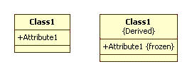
Showing Property
Among the element tag definitions, element tagged values and changeability attributes are shown in the view elements property section. The user can configure this property section to be shown or hidden.
Procedure for Showing Properties:
- Select from the diagram area an element for which to show the properties.
- Right-click and select the [Format] -> [Show Properties] menu.
Perform the steps above once again to hide the properties.
Note
- In the case of Changeability property value of AssociationEnd element is changeable or Ordering property value is UNORDERED, the relative property value is not be showed in the property part of diagram view element.
Showing Operation Signature
When displaying elements that contain operations such as class and subsystem, the parameter names and types for operations can be configured to be shown or hidden.
Procedure for Showing Operation Signature:
- Select from the diagram area an element to show the operation signature.
- Right-click and select the [Format] -> [Show Operation Signature] menu.
Perform the steps above once again to hide the operation signature.
Showing Compartment Visibility
Elements like classes, usecases, and subsystems that contain attributes, operations, literals, etc. have compartments to show their attributes and operations in diagram. Class has attribute and operation compartments, subsystem has an operation compartment, and enumeration has literal and operation compartments. Visibility of the elements displayed in these compartments can be configured to be shown or hidden.
Procedure for Showing Compartment Visibility:
- Select from the diagram area an element for which to show the compartment visibility.
- Right-click and select the [Format] -> [Show Compartment Visibility] menu.
- Perform the steps above once again to hide the compartment visibility.
Showing Compartment Stereotype
Elements like classes, usecases, and subsystems that contain attributes, operations, literals, etc. have compartments to show their attributes and operations in diagram. Class has attribute and operation compartments, subsystem has an operation compartment, and enumeration has literal and operation compartments. Stereotypes of the elements (attributes, operations, etc.) displayed in these compartments can be configured to be shown or hidden.
Procedure for Showing Compartment Stereotype:
- Select from the diagram area an element for which to show the compartment stereotype.
- Right-click and select the [Format] -> [Show Compartment Stereotypes] menu.
- Perform the steps above once again to hide the compartment stereotype.
Opening Diagram
In order to edit a diagram, the diagram must be opened. Once a diagram is opened, the tabs for the diagram are displayed. Select a tab to make the diagram active for editing.
Procedure for Opening Diagram:
- Search for the diagram to open in the model explorer or the diagram explorer.
- Double-click the diagram to open it. The diagram automatically becomes active.
Activates Diagram
In order to edit the specific diagram, you have to activate the diagram when you open several diagrams. If you want to activate the opened diagram, click the diagram on tab. In the case of having a lot of opened diagrams, you can activate the diagram as you selecting it in diagram list on pop-up menu.
??
??´????? ?????? ??I3???; E°??E ???????:
Procedure for the diagram activity with selected in menu:
- Right-click on the diagram tab and select the [Pages] menu.
- Selects a diagram name to activate among diagram lists as submenu.
Closing Diagram
Close a diagram if it no longer needs to be edited. Closing a diagram does not delete it. A closed diagram can be opened again at any time.
Procedure for Closing Diagram:
- Select the tab of the diagram to close to make the diagram active.
- Right-click on the tab and select the [Close Diagram] menu.
Procedure for Closing All Open Diagrams:
- Select the [View] -> [Close All Diagrams] menu.
Deleting Diagram
A diagram can be deleted if it is no longer needed. Please be careful, because deleting a diagram also deletes all information related to the diagram.
Procedure for Deleting Diagram:
- Select a diagram to delete, from the model explorer or the diagram explorer.
- Right-click and select the [Delete Model] menu.
Finding Element
Software models usually contain a large number of elements. Sometimes it becomes very difficult to locate wanted elements from among the many elements in a software model. The Find Element function can be used to search the wanted elements quickly.
Procedure for Finding Element:
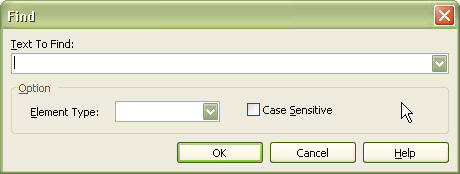
- Select the [Edit] -> [Find??] menu.
- At the Find dialog box, enter in the [Find what] field the full or partial name of the element to find. To limit the element types to find, select the element type from the [Options-Element type] menu. To match cases, check the [Options-Match case] item. Click the [OK] button.

- The find results are added in the [Messages] section of the information area. Double-click a message to find the related element.
Aligning Element
Elements laid out in diagram can be aligned in certain directions or with certain spacing.
Align Element Function
| Align Function | Description |
|---|---|
| Align the selected elements to the left. | |
| Align the selected elements to the right. | |
| Center the selected elements horizontally. | |
| Align the selected elements to the top. | |
| Align the selected elements to the bottom. | |
| Center the selected elements vertically. | |
| Evenly distribute the selected elements horizontally. | |
| Evenly distribute the selected elements vertically. | |
| Bring the selected elements to the front. | |
| Send the selected elements to the back. |
Procedure for Aligning Elements:
- Select the elements to align in the diagram area (two or more elements must be selected for aligning, except for ??Bring to Front?? and ??Send to Back??).
- Right-click and select the [Format] -> [Align] menu. Select the menu for the aligning method wanted.
Layout Diagram
In cases where the diagram elements are laid out in a disordered way, the elements can be automatically laid out for tidier display.
Procedure for Laying Out Diagram Elements:
- Make a diagram to layout the active diagram.
- Right-click and select the [Format] -> [Layout Diagram] menu.
Note
- The layout diagram function is not available for Sequence Diagram.
Configuring Zoom-In/Zoom-Out
If there are too many elements in the diagram area or if the element texts are too small, the diagram can be zoomed in or zoomed out for better view.
Procedure for Zooming In/Zooming Out Diagram:
- Select the [View] -> [Zoom] menu.
- Select the [Zoom-In] menu to zoom-in the diagram by one level (5%), or select the [Zoom-Out] menu to zoom-out by one level. To display the whole diagram in one screen, select the [Fit to Window] menu. You may also select a zooming ratio (50%, 75%, 100%, 125%, 150%, 175%, and 200%).
Saving Diagram as Image File
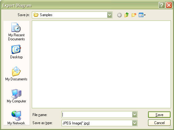
Diagrams can be saved as image files. StarUML? supports these image formats: JPEG (.jpg, .jpeg), bitmap (.bmp), metafile (.wmf), and extended metafile (.emf).
Procedure for Saving Diagram as Image:
- Make a diagram to save as image the active diagram.
- Select [File] -> [Export Diagram??] from the main menu.
- At the Save dialog box, enter the file name, select the file format, and then click the [Save] button.

Note
- In the case of metafile(.wmf) , some viewer may not display. It is recommended to used to the extended metafile(.emf).
Copying Diagram as bitmap
In order to insert a editing diagram to other document, the diagram image can be copied as bitmap. The diagram can be inserted to a document as editing image itself if copying it as bitmap, but it could have image distortion in the case of zoom in/out.
Procedure for copying diagram as bitmap:
- Make a diagram to copy as bitmap the active diagram.
- Select [Edit] -> [Copy Diagram As Bitmap] from the main menu.
Note
- Diagram information is copied to meta image if copying by Ctrl+C after selecting View. The meta image has no image distortion as zoon in/out in a document, but it could have difference with real image of the diagram in text editor program.
Navigating Diagram
If a diagram contains a lot of information, the diagram may become very large. In this case, only a limited section of the diagram can be shown on the screen. Agora Plastic? provides various methods to effectively navigate the diagram area, allowing the user to move to specific diagram locations quickly. The following methods can be used for navigating diagram.
Navigating with ScrollBar and Wheel
Moves for diagram domain what you want as using scroll bar. If you use wheel mouse, you can move to up and down by using mouse wheel.
Navigating with Bir??s Eye View
There is a small icon ![]() at the lower right-hand corner of the diagram area. Click this icon to see the entire diagram in a small area. Move to a diagram location while holding down the mouse button and then release the mouse button. This function is useful for navigating over a long distance.
at the lower right-hand corner of the diagram area. Click this icon to see the entire diagram in a small area. Move to a diagram location while holding down the mouse button and then release the mouse button. This function is useful for navigating over a long distance.
Navigating with Ctrl + Mouse
Hold down the Ctrl key and move the mouse to move the diagram. This function is useful for navigating over a short distance.
Configuring Default Diagram
A project can contain many diagrams. Among the many diagrams, there can be more than one default diagram, which is the most basic diagram of all. For instance, a diagram that expresses the overall structure of the project can be configured as the default diagram. Only Class Diagram, UseCase Diagram, Component Diagram or Deployment Diagram can be set as the default diagram. The default diagram is automatically opened when opening the project.
Procedure for Configuring Default Diagram:
- Select from the model explorer or the diagram explorer a diagram to configure as the default diagram.
- Select the [Properties] tab in the inspector area.
- At the property editor, check the ??DefaultDiagram?? property.
Organizing Model Structure
Creating Model Element
Model elements can also be created without being displayed in the diagram. Such a model is not displayed in any diagrams, and more than one view can be made later to represent it in diagrams.
Procedure for Creating Model Element:
- Select from the model explorer an element to contain the new model element.
- Right-click and select the [Add] menu and select an element type from the menu. Or, select the [Model] -> [Add] menu from the main menu.
- The new model element will be created under the selected model.
Deleting Model Element
If you delete a model element, many related elements are deleted together. Please exercise caution because deleting a model element results in deletion of the following elements.
- Included Model Elements: All model elements included in the model being deleted are also deleted.
- Related Model Elements: All relations such as Generalization, Association and Dependency related to the model element being deleted are also deleted.
- View Elements: All view elements that represent the model being deleted are also deleted.
Procedure for Deleting Model Element:
- Select from the model explorer a model element to delete, or select a view element from the diagram area to delete the model element represented by it.
- Hit [Ctrl+Del] or select the [Edit] -> [Delete Model] menu.
- The selected model element is deleted.
Moving Model Element
Model elements can be moved so as to be placed under other elements, such as by moving a class to be placed under another package or moving an attribute to be placed under another class. Model elements can be moved to be placed only under elements that can contain model elements. They cannot be moved to be placed under other types of elements.
Procedure for Moving Model Element:
- Select from the model explorer an element to move.
- Drag the element and drop it at the element that is to contain it.
Modify Model Element Order
The order between model elements can be modified to show intuitively configurations of software model. The order modification between model elements can be only among same kinds of elements. Also, it can be if sort of model navigator is only Storage Order.
??
Procedure for modify order of model element :
- Select an element to modify the order in model navigator.
- Move model element to a line as push [Move UP] or [Move Down] button.
Elements such as Attribute, Operation, Enumeration Literal which is expressing in Collection editor can be modified their order in Collection editor.
Procedure to modify order of model element in collection editor :
- Select upper element of an element to modify its order.
- Run collection editor as selecting [Model]->[Collection Editor…].
- Select tap which is relative in collection including element.
- Select element to modify the order.
- Modify the order of the model element as push [Move Up] or [Move Down] button. You can modify the order by using Ctrl+Cursor key.
Model Alignment
The structure of models in model navigator can be aligned as saving order or alphabet order. The aligned model is only shown by model navigator, the order among real models are not modified. In order to sort models, click [Align as saving order] or [Align as Alphabetical order]. If change model alignment way, the spreading statue of each node in model navigator is cancelled, and the top leveled node is spreaded.